Trusted Worldwide Questions & Answers
AutoDesk RVT_ELEC_01101 Dumps - Pass Autodesk Certified Professional in Revit for Electrical Design Exam in 2026
The AutoDesk RVT_ELEC_01101 exam is part of the Autodesk AEC Certifications path and focuses on the Autodesk Certified Professional in Revit for Electrical Design credential. It is designed for candidates who work with electrical design workflows in Revit and want to validate practical, job-ready skills. Earning this certification can help demonstrate your ability to handle real project tasks with confidence. It is a valuable credential for professionals who want to strengthen their standing in building design and coordination workflows.
| # | Exam Topics | Sub-Topics | Approximate Weightage (%) |
|---|---|---|---|
| 1 | Analysis | Electrical load review, circuit evaluation, design validation | 20% |
| 2 | Modeling | Electrical system placement, device layout, conduit and path setup | 25% |
| 3 | Documentation | Views and sheets, schedules, annotations and notes | 20% |
| 4 | Families | Family selection, parameter use, content management | 15% |
| 5 | Collaboration | Worksharing, coordination, file exchange and project updates | 20% |
This exam tests more than memorization. Candidates must understand Revit electrical design concepts, apply them in practical scenarios, and make accurate decisions under time pressure. It measures hands-on ability with modeling, documentation, families, analysis, and collaboration workflows that are common in real project environments.
How QA4Exam.com Helps You Pass
QA4Exam.com provides an Exam PDF with actual questions and answers plus an Online Practice Test for the AutoDesk RVT_ELEC_01101 exam. These materials help you study with real exam simulation, so you can become familiar with question style, pacing, and topic coverage before test day. The content is kept up to date and includes verified answers to support accurate preparation. The practice test also helps you improve time management and identify weak areas early. With focused review and realistic practice, you can prepare more confidently and aim to pass on your first attempt.
Frequently Asked Questions
1. Who should take the Autodesk Certified Professional in Revit for Electrical Design exam?
It is intended for candidates who work with electrical design in Revit and want to validate their practical skills as part of the Autodesk AEC Certifications track.
2. Is this exam difficult?
The exam can be challenging because it tests applied knowledge across multiple Revit electrical design areas, not just theory. Preparation and hands-on familiarity are important.
3. Do I need hands-on experience with Revit electrical design?
Yes, hands-on experience is strongly recommended because the exam focuses on practical skills in analysis, modeling, documentation, families, and collaboration.
4. Can I pass with only braindumps?
Braindumps alone are not the best approach. You should use them as a study aid along with practice and review so you understand the concepts behind the answers.
5. Are QA4Exam.com dumps enough or do I need other resources?
QA4Exam.com dumps and the Online Practice Test are designed to make preparation more effective, but combining them with your own Revit practice can improve confidence and retention.
6. Will the QA4Exam.com practice test help me pass in the first attempt?
It can help by giving you real exam simulation, verified answers, up-to-date questions, and time management practice, all of which support first-attempt readiness.
7. What format do the QA4Exam.com materials come in?
The product includes an Exam PDF with actual questions and answers and an Online Practice Test format for interactive preparation.
The questions for RVT_ELEC_01101 were last updated on Jul 18, 2026.
- Viewing page 1 out of 13 pages.
- Viewing questions 1-5 out of 63 questions
Refer to exhibits.
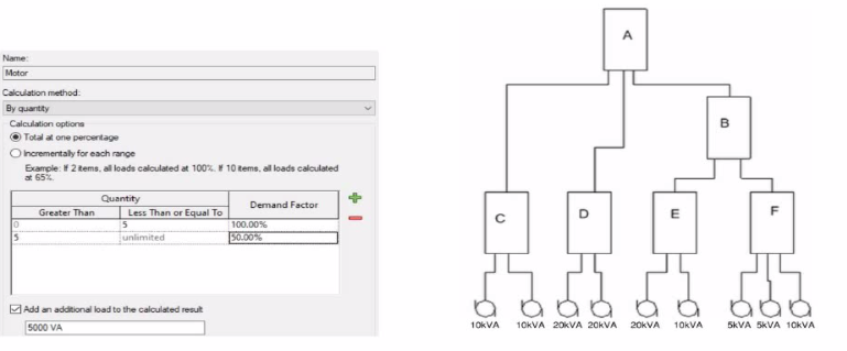
What is the demand load on Panel B?
In Revit Electrical, Demand Factors are applied through Load Classifications to compute an Estimated Demand Load rather than simply summing connected loads. The documentation states: ''You use demand factors to adjust the rating of the main service... Demand factors are assigned to load classifications, and load classifications are assigned to device connectors. The estimated load for a device is calculated by multiplying the load by the demand factor. ... The panel schedule can also display the load for each load classification.''
In the exhibit's Demand Factor definition (for the Motor classification), the Calculation method is By quantity with Total at one percentage selected. Two quantity ranges are defined: 0--5 items at 100% and 5--unlimited at 50%. An additional checkbox adds an extra fixed load of 5000 VA to the calculated result. (This follows Revit's behavior of applying the selected demand factor to the connected load and then adding any specified additional load to the result for that classification.)
Panel B feeds only panels E and F. The connected motor loads downstream are:
Panel E: 20 kVA + 10 kVA = 30 kVA
Panel F: 5 kVA + 5 kVA + 10 kVA = 20 kVA
Total connected motor load on B = 30 + 20 = 50 kVA (five items).
Because five items fall in the 0--5 range at 100%, the demand factor is 100% 50 kVA. Per the definition, add an additional load of 5000 VA (5 kVA) to the calculated result:
Demand Load on Panel B = 50 kVA 100% + 5 kVA = 55 kVA.
Therefore, the correct choice is 55 kVA.
References: Revit MEP Electrical documentation -- Demand Factors (assignment to load classifications, multiplication to compute estimated load, and display in panel schedules).
An electrical designer is working on a project with multiple buildings. The designer wants to organize the Project Browser by building For example, all views related to Building A will be sorted under Building A. and all views related to Building B will be sorted under Building B.
The designer decides to create a new parameter, assign it to views, and then sort the Project Browser according to the new parameter.
Which parameter should the designer use?
In Autodesk Revit, Project Parameters are used to add custom fields that apply to multiple elements within a specific project file --- such as views, sheets, or schedules. These parameters allow project teams to categorize, group, and sort information within the Project Browser or within schedules without editing families or external files.
As defined in the Revit MEP User's Guide and Revit Structure Parameters Chapter:
''Project parameters are specific to a single project file. Information stored in project parameters cannot be shared with other projects. A project parameter can be used, for example, to categorize views within a project.''
This statement directly confirms that project parameters are the correct tool for sorting or grouping views in the Project Browser. To organize elements (like views or sheets) by building, the designer can create a custom project parameter named ''Building'' and assign it to the View category. Once assigned, the parameter values (e.g., ''Building A'' or ''Building B'') can be filled in for each view.
The Smithsonian Facilities Revit Template Guide further supports this:
''View purpose is a Revit project parameter, providing a means for users to organize the many views that may exist in a BIM.''
Thus, using a project parameter allows users to add a ''Building'' field to each view, enabling customized browser organization (e.g., group views by Building A, Building B, etc.) without requiring shared parameters or family editing.
References:
Revit MEP User's Guide -- Chapter ''Parameters'' p. 1541--1543
Smithsonian Facilities Revit Template User's Guide -- Section 2.8.1 ''View Types and View Templates,'' p. 29
Autodesk Revit Electrical Design Essentials -- Parameter Management Section
An electrical designer has noticed lighting fixtures present in an architectural linked model. Which tool should be used to place an instance of those fixtures in the current electrical model while maintaining the position from the architectural model?
When lighting fixtures placed in an architectural linked model need to be replicated in the electrical model while maintaining their exact positions, the correct tool is Copy/Monitor.
This Revit feature allows the electrical designer to copy elements---like lighting fixtures---from a linked model into their project, while establishing a monitoring relationship between the original (architectural) and copied (electrical) instances.
From the Autodesk Revit MEP User's Guide -- Chapter 55 ''Multi-Discipline Coordination'' (pages 1349--1357):
''Use the Copy/Monitor tool to copy MEP fixtures from an architectural model into an MEP project, and monitor them for changes.'' (Revit MEP User's Guide, p. 1350)
''To copy fixtures from a linked model:
Click Collaborate tab Coordinate panel Copy/Monitor Select Link.
Select the linked architectural model in the drawing area.
Click Copy and select the lighting fixtures to copy.
Click Finish. Revit MEP copies the fixtures to the current project and establishes monitoring relationships.''* (Revit MEP User's Guide, p. 1356)
Behavior and Benefits:
The copied lighting fixtures maintain the same location, orientation, and type mapping as in the linked model.
Any changes (move, delete, or modify) made by the architect in the linked model will trigger a coordination review in the electrical model.
This ensures accurate positioning and easy coordination between disciplines.
''When you select a copied fixture in the current project, the monitor icon displays next to the fixture, indicating that it has a relationship with the original fixture in the linked model.'' (Revit MEP User's Guide, p. 1357)
''If copied fixtures are moved, changed, or deleted in the linked model, Revit MEP notifies the engineers of the changes during Coordination Review.'' (Revit MEP User's Guide, p. 1357)
How can an arrowhead be added to a lag leader line?
In Autodesk Revit for Electrical Design, arrowheads on leader lines---such as those used with tags, text notes, or annotations---are controlled through Type Properties, not through instance properties or free-end options.
According to the Revit MEP User's Guide -- Annotating Chapter (Chapter 47 and 42), the section ''Modifying Tags'' explains:
''Select the tag, and on the Properties palette, click (Edit Type). In the Type Properties dialog, select a value for Leader Arrowhead to add an arrowhead to the leader line.''
This confirms that the arrowhead is defined at the type level, meaning any change applies to all tags or text notes of that annotation type throughout the project. The Leader Arrowhead property allows the designer to choose from predefined arrowhead styles (like ''Filled Arrow,'' ''Dot,'' ''Tick Mark,'' etc.), which are defined globally under:
Manage tab Settings panel Additional Settings Arrowheads.
Furthermore, the document specifies under ''Leader Arrowhead Properties'':
''Sets the arrowhead shape on the leader line. The value is the name of the arrowhead style defined by the Arrowheads tool.''
This behavior applies to all annotation categories, including text notes, keynotes, material tags, and electrical device tags, maintaining consistency across all view types in an electrical project.
Therefore, Option C is the correct answer because arrowheads are configured via Type Properties, while the other options are inaccurate:
Option A (Free End) only defines leader attachment behavior.
Option B (Instance properties) does not include a ''Leader Arrowhead'' toggle.
Option D (Enable Leader Line) only adds or removes a leader line, not the arrowhead style.
References:
Autodesk Revit MEP User's Guide -- Chapter 47 ''Annotating,'' pp. 1040--1055
Autodesk Revit MEP User's Guide -- Chapter 42 ''Text Notes and Tags,'' pp. 936--949
Autodesk Revit Electrical Design Essentials -- ''Leader Arrowhead Properties and Annotation Standards''
An electrical designer wants to add a parameter to a lighting fixture schedule without editing the families. Which parameter type should the designer use?
In Revit Electrical Design workflows, when a designer wishes to add a parameter to a lighting fixture schedule without editing the families themselves, the proper approach is to use a Project Parameter.
The Revit MEP documentation clearly explains:
''To add a custom field to a schedule, you can create a custom parameter using the Parameter Properties dialog. Under Parameter Type, select Project parameter.''
This method links the parameter directly to the project and to all instances of the specified category (in this case, Lighting Fixtures), allowing it to appear in the schedule automatically without requiring any modification to the family files (.RFA).
In contrast:
Family Parameters apply only within the family file and are not schedulable across multiple families.
Global Parameters control dimensional or relational constraints, not schedule data.
Reporting Parameters are read-only and extract model information; they cannot be manually added to schedules.
Revit's scheduling workflow defines this process:
''On the Fields tab of the Sheet List Properties dialog, click Add Parameter... Under Parameter Type, select Project parameter.''
This same mechanism applies to lighting fixture schedules, as schedules and sheet lists share parameter structures in Revit. The new project parameter can then be sorted, filtered, and displayed in the schedule view for documentation or tagging purposes.
References:
Autodesk Revit MEP User's Guide -- Chapter 49 ''Preparing Construction Documents,'' pp. 1126--1128
Autodesk Revit Parameters Overview -- ''Project Parameters'' and ''Shared Parameters,'' pp. 1541--1543
Autodesk Revit Electrical Design Essentials -- Schedule and Parameter Management Section
Unlock All Questions for AutoDesk RVT_ELEC_01101 Exam
Full Exam Access, Actual Exam Questions, Validated Answers, Anytime Anywhere, No Download Limits, No Practice Limits
Get All 63 Questions & Answers