
Limited-Time Offer: Enjoy 50% Savings! - Ends In 0d 00h 00m 00s Coupon code: 50OFF
Welcome to QA4Exam

Practice questions demo

D-PVM-DS-01 Exam Dumps and Practice Questions

Questions 1 to 5 of the 40-question D-PVM-DS-01 bank, each with its correct answer and an explanation. This is page 1 of 8.

1 / 8

Actual Dell D-PVM-DS-01 Exam Questions

Question 1

In preparation for a bin file change to add I/O Modules and RF ports to an existing PowerMax 2000 system, Remote Proactive has placed a CE Lock on the frame.

While the CE Lock is in place, what configurations can be made on the frame?

Correct answer: C

During a planned hardware modification on a PowerMax array---such as the installation of additional physical I/O modules or remote replication (RF) ports---the internal architecture database must be carefully locked to protect the system's layout topology. When Remote Proactive or a Field Engineer initiates a binary configuration file (bin file) modification, a Customer Engineer (CE) Lock is applied to the specific frame or array identifier.

The primary function of this CE Lock is to serve as an authoritative safeguard that completely blocks all active storage provisioning and logical configuration operations across the entire array. While this lock is active, any attempts to perform masking operations, create or delete thin devices (TDEVs), or modify storage group boundaries via Solutions Enabler CLI (SYMCLI) or Unisphere will be rejected by the microcode controller. This absolute restriction is technically necessary because any alterations to the active configuration would create an immediate mismatch between the real-time layout database and the pre-compiled bin file structure awaiting execution. Allowing configuration changes to proceed with the lock in place would cause database corruption or validation failures, resulting in an aborted upgrade. Therefore, configuration operations are completely restricted until the lock is released.

Reference/Topics: Dell PowerMax Solutions Enabler Implementation Guide, Array Configuration Locks, Bin File Maintenance Workflows, Remote Support Operations.
Question 2

While designing a PowerMax 8500 system, the capacity requirements require 298 drives in a RAID 5(12+1) configuration.

What is the minimum number of node pairs that must be configured?

Correct answer: C

The Dell PowerMax 8500 system architecture scales out horizontally using two primary hardware building blocks: Node Pairs (compute engines) and Dynamic Media Enclosures (DMEs), which host the physical NVMe flash drives. A single Fornax DME provides a fixed physical capacity limit of exactly 48 drive slots. To accommodate the design requirement of 298 physical drives, the underlying infrastructure must provide an adequate number of physical enclosures. Dividing the total required drive count by the single enclosure slot capacity ($298 \div 48 = 6.208$) dictates that a minimum of 7 physical DMEs must be provisioned.

Furthermore, the PowerMax 8500 Dynamic Fabric architecture enforces strict topology interconnect rules regarding the ratio between compute resources and media enclosures. Specifically, the system requires a maximum configuration ratio where the number of active DMEs cannot exceed twice the number of configured node pairs ($\text{DMEs} \le 2 \times \text{Node Pairs}$). Applying this architectural threshold to the 7 required DMEs reveals that 3 node pairs can only support up to 6 DMEs ($3 \times 2 = 6$). Therefore, to legally connect and address 7 DMEs, the system must scale out to a minimum of 4 node pairs, which provides a maximum support capacity of up to 8 DMEs or 384 drives total.

Reference/Topics: Dell PowerMax Design Course Guide, PowerMax 8500 Hardware Scaling Rules, Dynamic Media Enclosure (DME) Topology, Node Pair to DME Ratios.

Question 3

A large financial institution has 25 PowerMax 2500 systems in the same data center and wants to deploy a centralized Unisphere server. The customer only has Linux servers with two-core, 2.5 GHz processor, 12 GB of memory, and 120 GB of disk space.

What is the minimum number of Unisphere servers that must be deployed for this environment?

Correct answer: A

Sizing a centralized Unisphere for PowerMax deployment requires balancing the performance metrics of the underlying host with the cumulative workload generated by the managed storage arrays. To manage a large-scale environment encompassing 25 PowerMax systems, standard Dell scaling guidelines recommend a "Large" or "Extra Large" Unisphere deployment profile, which mandates a minimum of 16 CPU cores and 64 GB of RAM on a single host instance to handle the massive performance collection database and object counts.

Because the customer's available Linux infrastructure is constrained to low-spec hardware nodes (2 CPU cores and 12 GB RAM), a single server cannot satisfy the resource requirements for a unified instance of this scale. Attempting to manage all 25 systems on one such node would lead to severe memory exhaustion and performance tracking failures. To safely accommodate the infrastructure, the architecture must scale out horizontally by splitting the 25 arrays across multiple smaller Unisphere server instances. Each small deployment profile can safely support up to 10 arrays. Dividing the 25 target systems across this threshold ($25 \div 10 = 2.5$) dictates that a minimum of 3 discrete Unisphere servers must be deployed to remain within supported resource limits.

Reference/Topics: Dell PowerMax Design Course Guide, Unisphere for PowerMax Sizing and Scalability, Server Resource Profiles, Centralized Management Topology.

Question 4

Due to limited space in the data center, your customer wants to deploy a new two-node pair PowerMax 2500 system using an existing third-party rack.

Which guidance best describes the support for a third-party rack installation?

Correct answer: D

Dell PowerMax 2500 architecture provides flexible deployment models, including support for installation into customer-supplied, standard 19-inch third-party racks to optimize existing data center floor space. However, strict configuration rules apply to ensure system integrity, structural stability, and proper thermal dynamics. All physical components belonging to the PowerMax 2500 system---including the compute nodes, internal Infiniband or Ethernet Dynamic Fabric switches, and Disk Array Enclosures (DAEs)---must be installed within a contiguous, unbroken vertical space inside the rack.

Interspersing or scattering PowerMax components around existing third-party server or networking hardware within the rack is strictly prohibited. This contiguous space requirement is mandated for two key technical reasons: first, to ensure that the pre-engineered internal system cabling lengths (InfiniBand/Ethernet fabric and power distribution loops) can securely reach their designated ports without strain; and second, to maintain a uniform front-to-back airflow containment field. Violating this layout compromises component cooling, increases thermal exhaust recirculation, and complicates serviceability and maintenance boundaries during field-replacement operations.

Reference/Topics: Dell PowerMax Design Course Guide, Physical Planning and Racking Requirements, Third-Party Rack Installation Guidelines.

Question 5

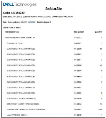
Refer to the exhibit.

Referring to the packing slip, extract the sizer ID from the Sales Order to put into PowerSizer.

Correct answer: B

In the Dell PowerMax configuration and design ecosystem, the PowerSizer tool is used to accurately model and generate precise hardware configurations based on specific workload requirements. When an order is placed or a configuration is successfully committed, the unique configuration session identifier---known as the Sizer ID---is embedded directly into the factory manufacturing and packing documentation via a series of tracking models representing each numeric position.

To extract the Sizer ID from the packing slip, a design architect decodes the quantities listed against the 'SIZER ID DIGIT [X] TRACKING MODEL' line items sequentially from Digit 1 through Digit 10. A baseline offset convention is applied where standard single-digit quantities represent their direct face value (for instance, a quantity of 1 indicates a value of 1, 3 indicates 3, 9 indicates 9, and 8 indicates 8). Special operational rules apply for specific placeholder boundaries: a quantity of 99 translates to a leading digit of 9, while a quantity of 100 represents a value of 0 or a sequence boundary alignment. Following this sequence sequentially from the first digit down to the tenth digit yields the definitive alphanumeric identifier prefix required by PowerSizer, matching the structure in option B (_913100925128). This validation ensures the correct system profile is synchronized for downstream deployment and provisioning verification.

Reference/Topics: Dell PowerMax Design Course Guide, PowerSizer Tool Integration, Design Resources and Environment, Order Verification Procedures.

Unlock all Dell D-PVM-DS-01 questions

Full exam access, validated answers, and unlimited practice with no download limits.