Trusted Worldwide Questions & Answers
Juniper JN0-650 Dumps - Pass Enterprise Routing and Switching, Professional Exam in 2026
The Juniper JN0-650 - Enterprise Routing and Switching, Professional exam is part of the Juniper Enterprise Routing and Switching certification track. It is designed for networking professionals who work with enterprise routing, switching, and related services in real-world environments. This exam validates your ability to apply core and advanced Juniper technologies across routing, switching, and enterprise network operations. Earning this certification can help demonstrate your readiness for professional-level enterprise network roles.
| # | Exam Topics | Sub-Topics | Approximate Weightage (%) |
|---|---|---|---|
| 1 | Interior Gateway Protocols (IGPs) | OSPF basics, IS-IS concepts, route redistribution, adjacency and convergence | 18% |
| 2 | BGP | Neighbor relationships, path selection, route policies, BGP troubleshooting | 18% |
| 3 | IP Multicast | Multicast routing concepts, PIM operation, group management, multicast forwarding | 12% |
| 4 | Ethernet Switching and Spanning Tree | VLANs, trunking, STP operation, loop prevention | 16% |
| 5 | Layer 2 Authentication and Access Control | 802.1X basics, port-based access control, authentication flow, security policy enforcement | 10% |
| 6 | IP Telephony Features | Voice traffic handling, QoS support, telephony integration, latency considerations | 8% |
| 7 | Class of service (CoS) | Traffic classification, queuing, scheduling, priority handling | 10% |
| 8 | EVPN | EVPN concepts, control-plane operation, Ethernet service delivery, multi-homing basics | 8% |
| Total | 100% | ||
This exam tests more than memorization. Candidates need a solid understanding of enterprise routing and switching concepts, plus the ability to interpret scenarios, analyze network behavior, and choose the correct Juniper approach. It also checks practical knowledge across routing, switching, multicast, security access, QoS, and EVPN-related topics.
How QA4Exam.com Helps You Pass
QA4Exam.com offers Exam PDF content with actual questions and answers, along with an Online Practice Test for the Juniper JN0-650 exam. These resources help you study with up-to-date questions that reflect the exam focus and format. The practice test gives you a real exam simulation so you can build confidence before test day. You also get verified answers and time management practice, which can make a big difference when aiming to pass on your first attempt.
Using both formats together helps you review concepts faster, identify weak areas, and prepare more efficiently for the Juniper Enterprise Routing and Switching, Professional exam.
Frequently Asked Questions
1. Who should take the Juniper JN0-650 exam?
The exam is intended for networking professionals pursuing the Juniper Enterprise Routing and Switching certification and those working with enterprise routing and switching technologies.
2. Is the Juniper JN0-650 exam difficult?
It can be challenging because it covers multiple enterprise networking areas, including routing, switching, multicast, CoS, and EVPN. Strong concept knowledge and practice are important.
3. Can I pass with only braindumps?
Braindumps alone are not a complete preparation method. They are best used as a supplement to help you review question patterns, reinforce concepts, and check your readiness.
4. Do I need hands-on experience for JN0-650?
Yes, hands-on experience is highly useful because the exam covers practical networking topics. Understanding how routing and switching behave in real environments can improve your performance.
5. Are QA4Exam.com dumps and practice tests enough to prepare?
They are very effective study tools, especially when used to validate your knowledge and practice exam-style questions. For best results, combine them with your own study and practical review.
6. How do these materials help me pass in the first attempt?
They help you study smarter by focusing on relevant questions, verified answers, and realistic practice. This builds confidence, improves speed, and reduces surprises on exam day.
7. What format do the QA4Exam.com materials come in?
QA4Exam.com provides an Exam PDF with questions and answers and an Online Practice Test. Both are designed to support flexible study and exam simulation.
8. Does the practice test help with time management?
Yes, the Online Practice Test is useful for timing yourself and learning how to pace your answers under exam conditions.
The questions for JN0-650 were last updated on Jul 20, 2026.
- Viewing page 1 out of 14 pages.
- Viewing questions 1-5 out of 69 questions
Exhibit
You are asked to configure VLAN load balancing on your network using MSTP. Referring to the exhibit, which two statements are correct? (Choose two.)
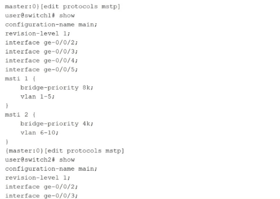
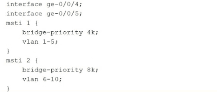
The exhibit shows the MSTP configuration for two switches, switch1 and switch2. MSTP allows you to group multiple VLANs into a single Multiple Spanning Tree Instance (MSTI), enabling different root bridges and topologies for different sets of VLANs.
Root Bridge Election (Option B): For any Spanning Tree instance, the switch with the lowest bridge priority is elected as the root bridge.
For msti 2, switch1 has a priority of 4k (4096), while switch2 has a priority of 8k (8192).
Since 4096 < 8192, switch1 is elected the root bridge for msti 2.
Failover Behavior (Option D): Spanning Tree is designed for redundancy. If a primary root bridge fails, the remaining switches in the network re-elect a new root based on the next lowest priority.
If switch2 goes down, switch1 becomes the only switch in the region.
Regardless of its original priority (4k or 8k), switch1 will take over as the root bridge for both msti 1 and msti 2 because there are no other contenders with a better (lower) priority.
Incorrect Statements: Option A is incorrect because for msti 1, switch2 has the lower priority (4k vs. 8k), making switch2 the root bridge. Option C is incorrect because it contradicts the fundamental high-availability nature of Spanning Tree.
Which two statements are correct about multicast routing tables? (Choose two.)
Junos OS uses specific routing tables for handling multicast traffic to ensure loop prevention through Reverse Path Forwarding (RPF) checks:
Multicast RPF (Option C): The inet.0 table is the default unicast routing table. In most standard multicast deployments, Protocol Independent Multicast (PIM) performs its RPF checks against this table to determine the upstream interface toward the multicast source.
Topology Differences (Option A): The inet.2 table is specifically designed for multicast RPF lookups when the multicast forwarding topology differs from the unicast forwarding topology. This is common in environments using Multiprotocol BGP (MBGP) where you might want multicast traffic to follow a different path than standard data traffic.
inet.1 Role (Option B): The inet.1 table is the multicast forwarding cache. It stores (S,G) and (*,G) entries for actual packet forwarding. Routing protocols like MBGP or IS-IS do not place routes directly into inet.1; instead, PIM uses information from inet.0 or inet.2 to populate inet.1.
IS-IS and OSPFv3 (Option D): These protocols place their IPv4/IPv6 unicast routes into inet.0 or inet6.0. They do not place routes into inet.2 'directly' unless specific RIB-group configurations or address families are enabled to share those routes for multicast RPF purposes.
Exhibit.
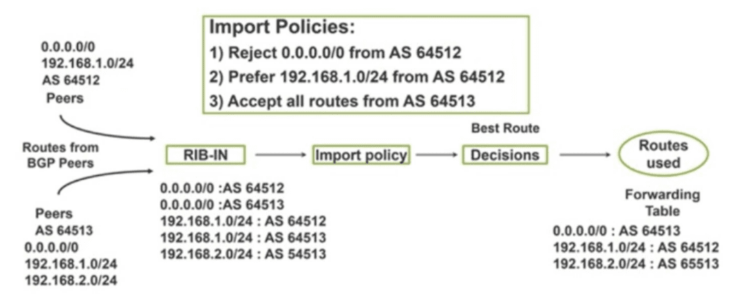
Referring to the exhibit, you see that the 0.0.0.0/0 route is coming from AS 64512.
What is the command to achieve this task?
The exhibit shows a BGP routing process where an Import Policy is being applied to routes received in the RIB-IN. Specifically, Policy 1 states: 'Reject 0.0.0.0/0 from AS 64512.'
In Junos OS, when a routing policy rejects a route, that route is not placed in the main routing table (inet.0) for active use. Instead, it becomes a hidden route. To verify that a specific peer is actually sending a route that is subsequently being rejected by your policy, you must use specific diagnostic commands:
Understanding 'Hidden' Routes: When a BGP route is received but fails to meet policy requirements (or has an unreachable next-hop), Junos keeps it in the BGP RIB-IN but marks it as 'hidden.' It will not appear in a standard show route command.
Command Logic (Option D): The command show route receive-protocol bgp
show route receive-protocol bgp
Adding the hidden keyword is the essential step to see the rejected default route and verify that AS 64512 is indeed sending it before the policy drops it.
Other Options:
Option A is incorrect because it only shows accepted routes.
Option B and C are used to filter the existing active routing table based on gateway or next-hop attributes, but they cannot show routes that have been rejected and excluded from that table.
While deploying class of service on an EX Series switch, what are two aspects of the scheduler? (Choose two.)
In Junos OS Class of Service (CoS), schedulers are the fundamental components used to manage the resources of individual egress queues. They determine how the switch handles traffic for a specific forwarding class as it waits to exit an interface.
Buffer Size (Option A): A scheduler defines the buffer size (memory allocation) for its assigned queue. This buffer holds packets during periods of congestion to prevent immediate packet loss. The size can be configured as a specific percentage of the total interface buffer, a temporal value in microseconds, or using the 'remainder' of available space.
Queue Priority (Option D): A scheduler identifies the priority of the queue. Junos supports multiple priority levels, such as low, medium-low, medium-high, and high. This setting dictates the order in which the transmission hardware services the queues; for example, high-priority queues are typically emptied before low-priority ones.
Why other options are incorrect: Interface rate-limiting (Option B) is typically managed at the interface level or through policers, not the scheduler itself, which focuses on queue-specific transmission rates. DiffServ code translation (Option C) is the responsibility of rewrite rules, which modify the packet header markings as they leave the switch.
Your OSPF network consists of a mix of 1GbE and 10GbE interfaces. By default, all interfaces have the same cost in your OSPF network. You are asked to ensure that the 10GbE interfaces are more preferred when available
In this scenario, which two statements would accomplish this behavior? (Choose two.)
OSPF determines the best path to a destination by calculating the metric (cost) of each link. By default, Junos OS uses a reference bandwidth of 100 Mbps to calculate this cost using the formula:

When the reference bandwidth is left at the default 100 Mbps, any interface with a speed of 100 Mbps or higher (including 1 GbE and 10 GbE) is assigned a cost of 1 because the minimum OSPF cost is 1. This results in equal-cost paths, preventing the router from preferring the faster 10 GbE link.
To ensure 10 GbE interfaces are preferred, you must create a cost differential:
Option A (Reference Bandwidth): By increasing the reference bandwidth to 10G (or higher), the calculation changes. For a 10 GbE link, the cost becomes $10,000 / 10,000 = 1$. For a 1 GbE link, the cost becomes $10,000 / 1,000 = 10$. Since OSPF prefers the path with the lowest cumulative cost, the 10 GbE link is now preferred.
Option D (Manual Metric): You can manually override the automatic cost calculation by assigning a higher metric specifically to the 1 GbE interfaces. If a 1 GbE interface is manually set to a cost of 50 and the 10 GbE interface remains at 1 (or is set to a lower value), the router will prioritize the 10 GbE path.
Option B is incorrect because a higher metric makes a path less preferred. Option C is incorrect because a 1G reference bandwidth would still result in both 1 GbE and 10 GbE interfaces having a cost of 1.
Unlock All Questions for Juniper JN0-650 Exam
Full Exam Access, Actual Exam Questions, Validated Answers, Anytime Anywhere, No Download Limits, No Practice Limits
Get All 69 Questions & Answers