
Limited-Time Offer: Enjoy 50% Savings! - Ends In 0d 00h 00m 00s Coupon code: 50OFF
Welcome to QA4Exam

Practice questions demo

4A0-265 Exam Dumps and Practice Questions

Questions 1 to 5 of the 40-question 4A0-265 bank, each with its correct answer and an explanation. This is page 1 of 8.

1 / 8

Actual Nokia 4A0-265 Exam Questions

Question 1

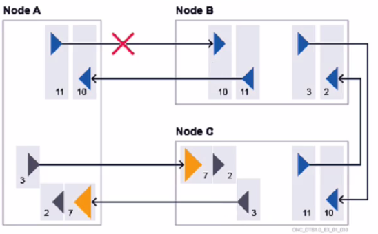
Consider the exhibit. A single directional fiber cut is occurring between two amplifiers in bidirectional configuration. Which node(s) will report a "LD Input LOS" alarm?
Correct answer: B

The exhibit shows a diagram of a network of nodes and edges, where a single directional fiber cut is occurring between two amplifiers in bidirectional configuration. The node that will report a ''LD Input LOS'' alarm is node B only.A ''LD Input LOS'' alarm indicates that the input signal to the laser diode (LD) of an amplifier is lost or below the threshold3. In this case, node B will not receive any signal from node A due to the fiber cut, and will generate this alarm. Node A will not report this alarm, because it can still receive a signal from node C through the other fiber. Node C will not report this alarm either, because it is not directly affected by the fiber cut between node A and node B.Reference:Nokia Optical Diagnostics and Troubleshooting Course | Nokia,Troubleshooting Guide for Synchronous Digital Hierarchy - Cisco
Question 2

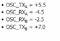
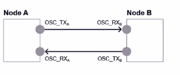
Consider the exhibit. Given the following power readings, what is the calculated span loss from Node A to Node B?

Correct answer: B

The exhibit shows a diagram of a network with two nodes, Node A and Node B, connected by a fiber span. The diagram also shows the power readings at different points of the span. The calculated span loss from Node A to Node B is the difference between the output power at Node A and the input power at Node B. According to the diagram, the output power at Node A is +3.5 dBm and the input power at Node B is -4.5 dBm. Therefore, the span loss from Node A to Node B is 3.5 - (-4.5) = 8.0 dB.


Question 3

Suppose a "Channel Absent" alarm is reported on an 1830 PSS node. What is the recommended order for the following troubleshooting steps?

Correct answer: B

The recommended order for the troubleshooting steps is B, as follows:

Retrieve the channel power trace.This step is useful to identify the affected channel and its power level, as well as to check if there are any fluctuations or anomalies in the power trace that could indicate a channel absent issue1.

Retrieve the cross-connection (XC) details and see what Wave Keys should be present.This step is necessary to verify which Wave Keys are expected to be present on the node, card, and port based on the XC configuration2.Wave Keys are unique identifiers for wavelength tracking that are encoded by Optical Transponders (OTs) into each service wavelength direction3.

Go to the suspected troubled node / card / port and look at Wave Keys (in / out). This step is helpful to compare the observed Wave Keys with the expected Wave Keys, and to locate the source of the problem.If a Wave Key is missing or mismatched, it means that there is a channel absent issue on that node, card, or port4.

Check observed Wave Keys against expected Wave Keys. This step is the final solution to resolve the issue and restore the normal operation of the node. The observed Wave Keys should match the expected Wave Keys based on the XC configuration.If not, the XC configuration should be corrected or the faulty node, card, or port should be replaced5.Reference:Nokia Optical Diagnostics and Troubleshooting Course | Nokia,Optical User Guide - Nokia,Alcatel-Lucent 1830 PSS-8 and PSS-16 Photonic Service Switch


Question 4

Which of the following statements about the alarm masking mechanism is TRUE?

Correct answer: D

The alarm masking mechanism is a feature of the 1830 PSS that prevents unnecessary alarms from being displayed on the GUI or forwarded to an external NMS when they are caused by a known fault or maintenance activity. For example, if an optical link is down due to a fiber cut, there is no need to show alarms for all the downstream interfaces that are affected by the link failure. The alarm masking mechanism hides these alarms until the root cause is resolved, and then shows them again if they persist. The alarm masking mechanism preserves the events' original time stamps when it masks/shows alarms, so that when an alarm is not masked anymore, the user can see the original date and time associated with the issue. This helps to identify and troubleshoot problems more accurately and efficiently.Reference:Optical User Guide - Nokia,Alcatel-Lucent 1830 PSS-8 and PSS-16 Photonic Service Switch


Question 5

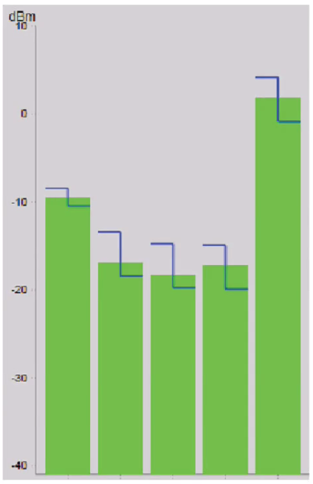
Consider the exhibit. What do the different colored green columns indicate?

Correct answer: C

The exhibit shows a graph of optical power levels measured at different interfaces throughout the optical path of a single wavelength. The different colored green columns indicate the optical power levels at different points along the optical path, such as the transmitter, the receiver, and the amplifiers. The graph also shows the expected power levels and the allowed deviation range for each point. The graph can be used to monitor the performance and quality of the optical signal and to identify any potential issues or anomalies. The other options are incorrect because they either describe a different type of graph or do not match the exhibit.Reference:Nokia Optical Diagnostics and Troubleshooting Course,OAM and Diagnostics Guide


Unlock all Nokia 4A0-265 questions

Full exam access, validated answers, and unlimited practice with no download limits.